The starting point · No engineering background needed
How do lifts work?
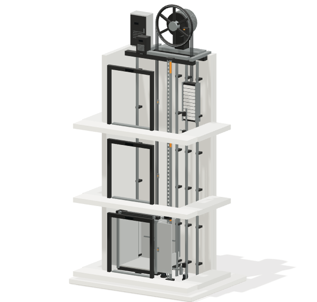
A lift—or elevator—moves a car between floors, guides its path and controls when it can travel or open its doors. Behind that familiar journey is a group of mechanical, electrical and safety systems working together.
Start with the whole picture here. Follow the links whenever you want to understand a component in more detail.
This lift is interactive.Click a floor to send it there. Drag to rotate the model.Explore the signals to see how doors, brakes and position are monitored.
Traction and hydraulic systems both move a car through a shaft, but they transmit force differently. Other arrangements exist, including screw-driven platform lifts. These simplified examples explain two common passenger-lift systems.
Traction lift
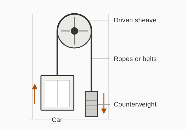
A driven sheave moves ropes or belts.
Simplified 1:1 suspension. A line represents a set of ropes or belts. Guides, brake, doors and protective devices are omitted.
A motor turns a grooved wheel called a traction sheave. Friction between the sheave and the suspension ropes or belts transfers force, moving the car and counterweight in opposite directions.
The counterweight balances the empty car plus a proportion of its rated load. That reduces the imbalance the motor must overcome; it does not make every journey perfectly balanced or remove friction and acceleration demands.
The suspension passes over the sheave rather than being stored on a winding drum. Roping ratios and machine positions vary between installations.
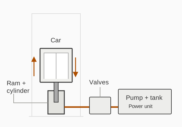
Conventional direct-acting example. Flow paths are conceptual; protective valves and detailed circuit connections are omitted.
In a conventional hydraulic lift, an electric motor drives a pump that sends fluid into a cylinder. Pressure acting on the ram’s effective area produces an upward force and raises the car.
For normal descent, the load pushes fluid back towards the tank through a controlled valve path. The pump usually does not need to run for this gravity-lowering journey.
Some installations use ropes and pulleys between ram and car, rather than a ram acting directly beneath the car. Hydraulic circuits and energy-control arrangements also vary.
This is a simplified example of normal passenger operation. The detailed sequence depends on the control system and installation.
01
The controller receives a call
A landing or car button sends a request. The controller decides when to serve it using the lift’s position, direction, other calls and operating conditions.
For normal travel between floors, the relevant doors must be closed and locked, and the required safety conditions must be satisfied. Door movement and proving a lock are different functions.
On a typical modern traction lift, the drive controls motor torque and speed while brake operation is coordinated with it. A hydraulic system instead coordinates its pump and valves to control fluid movement.
Sensors and feedback tell the controls where the car is and, depending on the system, how it is moving. The lift slows and levels at the intended landing.
The installation coordinates stopping, holding and door opening at the landing. Brake and valve arrangements differ, and some lifts have specially controlled levelling functions within the door zone.
A component has a job. The lift needs them to work together.
Car, shaft and guides
The car carries passengers or the permitted load. It travels in the shaft, with rails and guides keeping it aligned. The guides and suspension perform different jobs.
The controller coordinates the installation. A variable-frequency drive, where fitted, regulates the motor’s electrical supply to control motion. They are distinct functions.
Car doors travel with the car; landing doors guard the openings at each floor. The door operator moves the doors, while locks and contacts establish separate conditions.
Normal motion control, holding at a floor and protection against abnormal movement are related but distinct. The devices fitted depend on the lift’s design and installation.
Doors and safety conditions
Locks and protective circuits help prevent normal travel unless the required conditions are met. Entrance detectors help with door operation; they do not reliably detect every thin item, such as a dog lead.
In a conventional arrangement, an overspeed governor can trigger safety gear that grips the guide rails. This is separate from the machine brake used in normal operation.
A hydraulic rupture valve can act on excessive outward flow at the cylinder. Protection against unintended car movement with doors open has a separate role; it is not simply another name for overspeed protection.
You can follow the course from first principles or go straight to the component you are curious about. Lessons include diagrams, explanations and links to helpful background.
These explanations are for understanding the equipment. They are not instructions for accessing lift machinery, adjusting controls, testing safety devices or carrying out repairs.
Common questions
A few useful distinctions.
Is an elevator different from a lift?
In this context they refer to the same equipment. “Lift” is usual in British English and “elevator” in American English. The operating principle depends on the installation, rather than the word used for it.
Do all lifts have a counterweight?
No. A counterweight is a feature of many traction installations. A conventional hydraulic lift instead uses pressure acting on a ram, and other drive arrangements exist.
Yes. Conventional hydraulic lifts use an electric motor to drive the pump, with electrical controls coordinating operation. Gravity-lowering descent does not mean that the whole installation operates without electricity.
Is a machine-room-less lift a different lifting principle?
“Machine-room-less” describes where equipment is accommodated. A traction machine can be fitted within the shaft rather than a separate machine room; it still uses a traction principle. Equipment location and lifting method are different questions.
Why might a lift stop when nothing looks wrong?
A missing door-lock signal, another protective condition or an equipment fault can prevent travel. Similar symptoms can have different causes. A stopped lift is not a reason to force doors or reset machinery yourself.